
How VIO Works
A Step-by-Step Explanation of Drone Navigation Without GPS
UNIBIRD
11/26/20252 min read

Think of the VIO module as a small SLAM brain sitting on the drone, telling it:
“Where am I now? How fast am I moving? Which way am I facing?”
even when there is no GPS.
I’ll explain it using the SLAM idea step by step.
1. From SLAM to VIO: the relationship
SLAM = Simultaneous Localization and Mapping
Localization: estimate the robot’s position and orientation (pose).
Mapping: build a map of the environment at the same time.
SLAM usually uses sensors like cameras, lidar, IMU, etc.
VIO = Visual–Inertial Odometry
Visual: uses camera images.
Inertial: uses IMU (accelerometers + gyroscopes).
Odometry: track motion over time (how pose changes).
So, VIO is basically the localization / motion-estimation part of a SLAM system, using camera + IMU.
Some VIO systems also build a local map, but their main focus is: give very fast, real-time pose for control.
2. What is inside a VIO module on a drone?
Usually a VIO module includes:
Camera: Monocular (1 camera) or stereo (2 cameras).
Points forward, downward, or has a wide FOV.
IMU: 3-axis accelerometer, 3-axis gyroscope.
Processor: Runs the SLAM / VIO algorithm. Often outputs pose in some coordinate frame (x, y, z, roll, pitch, yaw).
Interfaces: Sends pose, velocity, and quality/health to the flight controller (PX4, Ardupilot, etc).
3. How it works, using SLAM concepts
Let’s walk through the pipeline in SLAM terms.
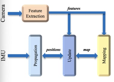
3.1 Front-end: feature tracking from camera
The camera captures an image.
The algorithm detects features (corners, textured points) in the image.
In the next frame, it tries to match the same features again.
By seeing how these feature points move between frames, it can estimate the relative camera motion.
3.2 IMU integration: predict motion
In parallel, the IMU runs at high frequency:
Gyro → measures angular velocity → predicts rotations.
Accelerometer → measures linear acceleration → predicts velocity and position after integration.
IMU alone drifts quickly, but over very short times (a few milliseconds) it gives a good prediction.
So VIO uses IMU as a prediction (prior):
“In the next 10 ms I expect to turn 1° right and move 2 cm forward.”
3.3 Sensor fusion: visual + inertial
Then the system combines:
Visual constraints: from feature matches in images.
Inertial constraints: from integrating IMU.
This fusion is often done with:
An Extended Kalman Filter (EKF), or
A nonlinear optimizer / factor graph (Bundle Adjustment, Sliding-Window optimization).
Result:
Best estimate of:
Position: (x, y, z)
Orientation: (roll, pitch, yaw / quaternion)
Velocity: (vx, vy, vz)
Plus some estimate of the uncertainty, often expressed as covariance or a tracking “quality” score. This is the localization part of SLAM.
4. How the drone actually uses the VIO output
From the drone’s point of view, the VIO module is just a position/velocity sensor, like a “virtual GPS.”
The VIO module sends data to the flight controller, for example:
Position [m] in some local frame (e.g., NED or ENU).
Velocity [m/s].
Attitude (quaternion or Euler angles).
Quality / tracking status (OK / LOST / DEGRADED).
The flight controller then:
Uses these as inputs to its state estimator (EKF).
Runs the position and attitude control loops:
Position hold.
Waypoint following.
Trajectory tracking.
So in GPS-denied environments (indoors, tunnels, jamming):
GPS is missing or unusable.
VIO becomes the main source for position.
Altitude may also use barometer / rangefinder, but horizontal (x,y) is VIO.